VFD Controllers for Fan Sizing and Setup
A fan running at full speed is not automatically moving the right amount of air. It may be over-ventilating a warehouse during mild weather, pulling excessive negative pressure in a greenhouse, or wasting power in a manufacturing exhaust system after production slows. VFD controllers give facility teams a practical way to match fan speed to the actual heat load, air-exchange requirement, and static-pressure conditions at that moment.
For commercial and industrial ventilation, a variable frequency drive is more than an energy-saving accessory. Correctly selected and commissioned, it can reduce mechanical stress at startup, improve temperature control, maintain building pressure, and provide the operating data needed to manage complex facilities. Incorrectly applied, it can cause nuisance faults, motor overheating, electrical noise, and disappointing airflow. The difference comes down to matching the drive, motor, fan, controls, and operating environment as one system.
What VFD Controllers Do in a Ventilation System
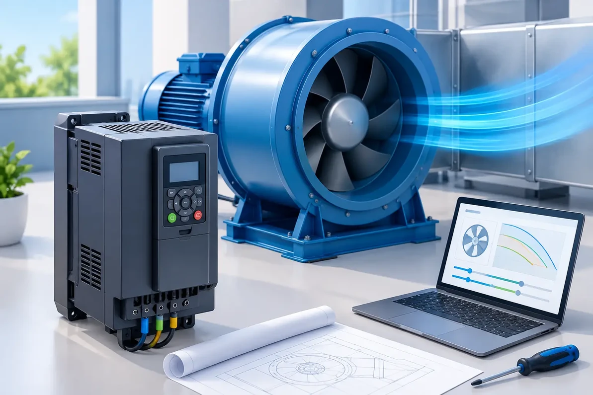
A variable frequency drive changes the frequency and voltage supplied to an AC motor. That allows the motor - and the fan connected to it - to run below or, where equipment permits, at its rated speed. Instead of repeatedly cycling a large exhaust fan on and off, the drive can maintain a controlled, lower fan speed when demand is light and increase output when temperature, humidity, pressure, or process load rises.
Fan laws explain why this control can produce meaningful energy savings. Airflow changes roughly in direct proportion to fan speed. Static pressure changes with the square of speed, while power demand changes with the cube of speed. A modest speed reduction can therefore create a substantial reduction in electrical demand. Actual savings depend on the fan curve, system resistance, run hours, and control strategy, but the physics make variable-speed control especially valuable for fans that rarely need full output.
This is also why a VFD should not be selected solely by horsepower. A drive has to support the actual motor load and operating conditions, not just the number printed on a fan nameplate.
Start With the Motor and Fan Nameplate
The first step is confirming that the motor is suitable for VFD operation. Most modern three-phase induction motors can operate on a properly configured drive, particularly when they are identified as inverter-duty. Older motors can sometimes be used, but insulation condition, lead length, motor cooling, and low-speed operating requirements need closer review.
Collect the motor voltage, phase, horsepower, full-load amps, service factor, RPM, and enclosure type. The VFD input voltage must match the available electrical service, while the drive output must be appropriate for the motor voltage. A 480V three-phase drive is not a substitute for a 208V system, and a standard VFD is generally not the right answer for a typical single-phase PSC fan motor.
Motor current is especially important. Drive selection should be based on the motor full-load amperage and the drive's continuous output-current rating, with appropriate consideration for ambient temperature, altitude, and load type. Fans are usually variable-torque loads, which often permit a standard variable-torque-rated drive. Heavy starting loads, conveyors, pumps with unusual duty cycles, or other non-fan equipment may require different sizing criteria.
One VFD can sometimes operate multiple fan motors, but only when the application is engineered correctly. The combined motor current must remain within the drive rating, every motor needs proper overload protection, and all connected fans will generally run at the same speed. For zones needing independent airflow control, individual drives or electronically commutated fan systems are often the better design.
Do Not Treat EC Motors Like Standard AC Motors
EC and brushless DC motors have their own electronic speed-control architecture. Many accept a 0-10V, PWM, or communications control signal directly and do not use a conventional VFD. Applying the wrong controller can damage equipment or simply fail to provide control. Always confirm the fan manufacturer's approved control method before specifying a drive.
Size for the Real Operating Point, Not Just Full Speed
A fan's rated CFM is only meaningful at a stated static pressure. As filters load, louvers add resistance, duct routing changes, or make-up air becomes restricted, the operating point moves. The VFD can help compensate, but it cannot overcome a fundamentally undersized fan, a blocked intake path, or inadequate make-up air.
Before setting a speed range, identify the required airflow, expected static pressure, temperature range, and minimum ventilation requirement. For a warehouse exhaust application, the control point may be indoor temperature. In a manufacturing area, it could be process capture velocity or building pressure. A greenhouse may require staged airflow based on temperature and humidity, while a crypto mining or data center project may need supply and exhaust fans to track heat load and maintain safe equipment inlet temperatures.
Maximum speed should normally be limited to the fan manufacturer's approved RPM. Increasing frequency above 60 Hz may look like an easy way to gain CFM, but it can overload the motor, exceed fan wheel limits, raise sound levels, and sharply increase horsepower demand. It is not a field adjustment to make without verified fan-performance data.
Minimum speed needs just as much attention. At very low RPM, some motors do not receive enough shaft-mounted fan cooling. Belt-driven fans may encounter belt slip, poor belt wrap, or inadequate airflow through a process hood. Certain fans can create objectionable resonance at specific speeds. Establish a minimum stable operating frequency during commissioning rather than assuming every fan can operate effectively at 10 Hz.
Choose an Enclosure That Fits the Installation
The drive enclosure has to match the environment, not just the electrical room. A clean, conditioned mechanical space may allow a standard NEMA 1 enclosure. Warehouse floors, washdown areas, barns, cultivation facilities, rooftops, and dusty production spaces frequently require a more protective enclosure and careful heat management.
Drives create heat, and an enclosed panel can overheat even when the VFD is technically rated for the job. Check the enclosure cooling method, mounting clearances, panel solar exposure, airborne dust, and expected ambient temperature. In high-heat applications, relocating the drive to a cleaner conditioned area or using a properly engineered remote-control arrangement may be more reliable than installing electronics beside the exhaust fan.
For outdoor systems, consider moisture, direct sun, condensation, wind-driven debris, and service access. A higher enclosure rating protects against contaminants, but it may also retain more heat. There is no universal enclosure choice - the correct answer depends on the site and the maintenance plan.
Build the Control Strategy Around the Ventilation Goal
A VFD is only as useful as the signal telling it what to do. Manual speed control may be sufficient for a simple seasonal exhaust fan. Most demanding applications benefit from automatic control using temperature sensors, humidity sensors, differential-pressure sensors, CO or process sensors, building automation signals, or a combination of inputs.
Pressure control is often valuable where exhaust must coordinate with make-up air. If exhaust fans accelerate without adequate replacement air, the building can develop excessive negative pressure. Doors become difficult to open, combustion appliances can be affected, and the fan may move less air than expected. Conversely, an over-pressurized building can push conditioned air and moisture into unwanted locations.
For multi-fan systems, staging is frequently more efficient than running every fan at a low speed. A practical sequence may operate one fan across a broad speed range before enabling the next fan as load rises. The best sequence depends on fan efficiency, redundancy requirements, sound limits, and the airflow needed during failure or maintenance conditions.
Electrical Details That Prevent Expensive Problems
VFD output cables and fast switching frequencies can introduce electrical stress, particularly on long motor leads. Depending on cable length, motor construction, and drive manufacturer requirements, the installation may need a load reactor, dV/dt filter, or sine-wave filter. These components help protect motor insulation and reduce reflected-wave voltage issues.
Grounding, shielded control wiring where appropriate, separation between power and low-voltage signal cables, and correctly installed bypass equipment are not minor installation details. They directly affect reliability. If the VFD is tied to building automation, coordinate the start/stop logic, speed reference, alarm contacts, fault reset method, and loss-of-communication response before startup.
A bypass can be useful for critical ventilation, but it must be designed so the motor is never connected to utility power and VFD output at the same time. It also needs a clear operating procedure. A bypass is not a substitute for troubleshooting a poorly designed control system.
Commissioning Is Where Performance Becomes Measurable
After installation, program the motor nameplate data accurately. Set acceleration and deceleration ramps to avoid belt shock, duct pressure surges, or nuisance overcurrent faults. Establish minimum and maximum frequencies, confirm rotation, verify safeties, and test the system under realistic operating conditions.
Measure airflow, static pressure, motor current, temperature response, and building pressure where applicable. Review fault history after the first operating period. A drive that runs without faulting is not necessarily delivering the ventilation result the project requires.
Factory Fans Direct evaluates ventilation systems as complete airflow designs, including fan performance, motor compatibility, static pressure, heat load, make-up air, and the appropriate VFD control approach. For facilities where downtime, heat accumulation, crop conditions, or equipment cooling are on the line, that engineering review can prevent a costly mismatch before equipment is installed.
The most useful next step is to document the fan and motor nameplates, electrical service, target CFM, estimated static pressure, and control objective. Those few details turn a generic drive purchase into a VFD control plan that can be set up, commissioned, and maintained with confidence.
Factory Fans Direct - Commercial & Industrial Ventilation & Cooling Experts | Contact Mike Miller VP Engineering at Factory Fans Direct for a FREE Project Evaluation 888-849-1233 | Mike@FactoryFansDirect.com
Recent Posts
-

The BLUE WAVE Supports Commercial & Industrial ecoPOWER Hybrid Turbine Ventilation
A hot production floor, warehouse, or agricultural building rarely has one ventilation problem. Heat …8th Nov 2026 -
AI Smart ecoPOWER Hybrid Turbine Ventilation for LEED Projects
A LEED ventilation strategy cannot be built around a brochure claim or a fan wattage number alone. A …8th Nov 2026 -
AI LEED Projects Specify ecoPOWER Hybrid Ventilation
A rooftop exhaust strategy can make or break a net-zero model long before a building opens. When AI …8th Nov 2026