
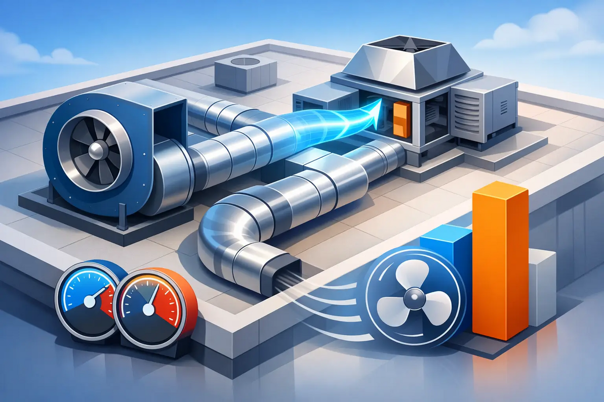
Commercial Ventilation 101: Static Pressure and CFM
A fan rated at 20,000 CFM does not deliver 20,000 CFM in every building. That published number only applies at a stated static pressure, air density, fan speed, and test condition. Commercial Ventilation 101: learn how static pressure and temperature affect CFM before selecting exhaust, supply, roof-mounted, or wall-mounted equipment for a warehouse, manufacturing plant, grow facility, agricultural building, or equipment room.
The practical issue is simple: if the real system creates more resistance than the fan was selected to overcome, actual airflow falls. If the air is hotter, thinner, or at a high elevation, the fan's pressure capability and cooling performance can also change. A successful ventilation design matches the fan curve to the building's real operating conditions, not just the largest CFM number on a product page.
What CFM Actually Tells You
CFM means cubic feet per minute. It measures air volume moved, which makes it useful for calculating air changes, exhausting heat, clearing humidity, controlling odors, and replacing contaminated air. But CFM is only one side of fan performance.
Every fan has a performance curve. The curve shows how much airflow the fan can move at different levels of static pressure. At nearly zero static pressure, a fan may produce its highest CFM. As system resistance rises, the operating point moves along the curve and CFM decreases. Eventually, the fan reaches shutoff pressure, where it can no longer move useful air through the system.
This is why two fans with the same free-air CFM rating can perform very differently. A high-volume propeller fan can be an excellent choice for a large open wall opening with a guard and shutter. That same fan may be a poor choice for a ducted exhaust run, restrictive louver, filtration bank, light trap, evaporative media wall, or backdraft damper. Those applications require a fan designed to produce pressure as well as volume.
Commercial Ventilation 101: Understanding Static Pressure
Static pressure is the resistance air encounters as it moves through a ventilation system. It is commonly measured in inches of water gauge, written as in. w.g. or inches SP. The higher the static pressure, the harder the fan must work to deliver the required CFM.
Resistance is created by every component in the airflow path. An open wall fan has relatively little resistance. A system with ductwork, elbows, transitions, weather hoods, louvers, motorized dampers, screens, filters, sound attenuators, intake openings, and discharge restrictions has much more.
The major contributors to static pressure usually include:
- Intake louvers, bird screens, and weather hoods
- Duct length, duct diameter, fittings, and sharp transitions
- Filters, light traps, evaporative cooling pads, and dampers
- Exhaust shutters, roof curbs, stack caps, and discharge accessories
- Insufficient make-up air openings or a building operating under negative pressure
A common field mistake is selecting the fan first and estimating static pressure later. The correct process is the reverse. Calculate the required airflow, map the complete intake and discharge path, estimate total external static pressure, then select a fan that delivers the required CFM at that pressure.
For example, a 15,000 CFM fan rated at 0.00 in. w.g. may only produce 11,000 CFM at 0.25 in. w.g. If the facility needs 15,000 CFM for heat removal, the installation is now 27 percent short on exhaust capacity. That gap can mean higher indoor temperatures, poor humidity control, hot equipment aisles, or a grow room that cannot hold environmental setpoints.
The System Curve Determines the Operating Point
The fan curve is only half of the selection. The other half is the system curve. A system curve represents how much resistance the building and ventilation components create at different airflow levels. In most ventilation systems, pressure rises approximately with the square of airflow.
That relationship matters when a system is modified. Doubling airflow does not merely double resistance. It can increase pressure requirement by roughly four times. A fan that appears oversized at 8,000 CFM may be unable to reach 16,000 CFM once duct losses and restrictive accessories are included.
The fan operates where its fan curve intersects the system curve. When a dirty filter loads up, a damper closes too far, a louver becomes clogged with debris, or added equipment restricts the opening, the system curve shifts upward. The operating point shifts left, and CFM drops.
Variable frequency drives provide useful control, but they do not erase pressure limitations. Reducing fan speed reduces CFM roughly in proportion to speed, while pressure capability changes with the square of speed. A VFD is highly effective for matching changing heat loads, reducing noise, and saving energy during part-load operation. It still requires a fan and motor selected with enough pressure and horsepower margin at the design condition.
How Temperature Changes Airflow and Cooling Capacity
Temperature affects ventilation in two ways: it changes air density and it changes the heat-removal requirement. These effects are related, but they are not the same thing.
Hot air is less dense than cool air. Standard fan ratings are generally based on standard air density, commonly about 0.075 pounds per cubic foot at sea level and approximately 70°F. At higher temperatures, the same cubic foot of air contains less mass. Since fans create pressure by accelerating air mass, a fan operating in hot, low-density air develops less static pressure than it does under standard conditions.
In a low-resistance application, the measured volumetric airflow may remain close to the published CFM and can even increase slightly. However, the fan has less pressure capability available to overcome restrictive ductwork, filters, louvers, or process equipment. In high-static applications, that reduction can move the operating point enough to reduce delivered CFM.
More critically, hot air has less heat-carrying mass per cubic foot. Cooling a high-temperature facility is not only about moving a target CFM number. It is about removing the heat load. When server racks, mining equipment, furnaces, compressors, lighting, people, or machinery add significant heat, design must account for temperature rise, air density, equipment heat output, and the intended indoor setpoint.
A facility at 110°F needs a different evaluation than a warehouse at 80°F, even if both have the same floor area. The hotter facility may need more exhaust volume, larger make-up air openings, higher-static fans, staged controls, or a different cooling strategy altogether. Direct exhaust ventilation may be appropriate in one case, while evaporative cooling, filtered supply air, recirculation fans, or mechanical cooling may be needed in another.
Altitude, Motor Load, and Fan Selection
High altitude produces a similar density effect. Air at elevation is less dense, so the fan develops less static pressure and moves less mass airflow at a given CFM. This matters in mountain states, but it also matters wherever high-temperature process air is being exhausted.
There is a trade-off. Lower-density air generally reduces brake horsepower demand, which can reduce motor loading. Yet lower density also reduces the fan's pressure performance. A motor may appear comfortably sized while the fan fails to deliver the required airflow through the actual system.
For demanding applications, use the manufacturer's certified fan curve and performance data, then apply density corrections when required. Confirm the fan's operating point, motor horsepower, drive arrangement, permissible speed, sound level, and material suitability for the air stream. Corrosive grow environments, livestock buildings, welding operations, and high-temperature equipment rooms may also require specialized coatings, motors, belts, guards, or control packages.
Make-Up Air Is Part of the CFM Calculation
Exhaust fans cannot remove air that the building cannot replace. A building with inadequate make-up air becomes negatively pressurized. The fan sees higher resistance, airflow declines, doors become difficult to open, combustion equipment can be affected, and unconditioned air enters through unintended cracks.
For every exhaust design, calculate where replacement air will enter and how much pressure loss that path creates. A large intake louver with low face velocity may provide adequate make-up air with minimal pressure drop. A small, screened opening can become the system bottleneck. In conditioned or process-sensitive buildings, a dedicated make-up air unit may be necessary to provide tempered, filtered, or humidity-controlled replacement air.
Do not assume multiple fans automatically add their rated CFM. Fans operating in parallel can interact, especially when they share common ductwork, roof plenums, or limited intake area. The final design should evaluate the combined system, fan staging sequence, and failure mode if one fan is offline.
Field Checks That Prevent Underperforming Systems
Before ordering equipment, document the intended CFM, design temperature, elevation, room dimensions, heat sources, operating schedule, and airflow path. Identify every component between the building and the fan discharge. Cut sheets for louvers, dampers, filters, ducts, and accessories should be reviewed for pressure-drop data rather than treated as incidental hardware.
After installation, verify performance. Measure static pressure at representative locations, confirm fan rotation and speed, inspect shutters and dampers for full travel, and check that make-up air openings are unobstructed. If actual airflow is lower than expected, the answer is rarely to install a bigger fan without diagnosing the restriction. Correcting an undersized louver, dirty filter, poor transition, closed damper, or inadequate intake may restore the required CFM with far less cost and energy use.
Factory Fans Direct provides commercial and industrial ventilation design support for projects where fan curves, static pressure, temperature, make-up air, and equipment selection must work together. Contact Mike Miller, VP Engineering, for a FREE Project Evaluation at 888-849-1233.
Factory Fans Direct - Commercial & Industrial Ventilation & Cooling Experts | Contact Mike Miller VP Engineering at Factory Fans Direct for a FREE Project Evaluation 888-849-1233 | Mike@FactoryFansDirect.com
Recent Posts
-

Smart Buildings Architects Recommend Edmonds ecoPOWER Hybrid Ventilation
A rooftop ventilator should not force an all-or-nothing energy decision. Smart Buildings Architects …7th Sep 2026 -
Smart Industrial Buildings Use Edmonds ecoPOWER Hybrid Ventilation
A roof exhaust system can be the difference between a plant that controls heat at the source and one …7th Sep 2026 -
Smart Commercial Buildings Use Edmonds Hybrid Ventilation
A rooftop exhaust fan that only performs when the wind blows is not a complete ventilation strategy. …7th Sep 2026